
Material composition
Traditional CLT and GLT materials were generally composed of softer spruce/pine and Douglas fir wood species from Canada and Northwestern U.S. However, more recently, many companies in the southern U.S. have been transitioning to use Southern yellow pine as an alternative due to cost and availability. The higher density and grain structure of southern yellow pine makes machinability dramatically different and has a negative effect on tool longevity. Regardless of wood species, the final product after glue lamination can be extremely abrasive to cut. Adhesive products have high resin content, which generates heat during the machining process. This problem is exaggerated at deeper depths of cut with less efficient material removal rates.
Heat generation causes premature cutting-edge failure, resulting in poor quality and added cutting pressures on the machine spindle and holding systems. Therefore, it is critical to design cutting tools and holding systems with added features to increase rigidity and chip extraction.
Extended length router tooling
Solid carbide
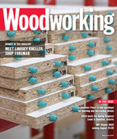
Image 1 shows a 40 mm diameter by 330 mm long solid carbide router tool designed for deep machining in mass timber components. Solid carbide geometry provides the absolute best cut quality and chip extraction when machining at high feed rates. Spiral flute geometry and serrated cutting edges reduce cutting pressures, improve cut quality and allow machines to cut at optimal feed rates to reduce cycle time. However, they do have limitations with regards to diameter and length. Carbide raw material is expensive and difficult to produce at diameters over 40 mm and the cutting-edge lengths are generally maximized at 330 mm length. Tools can be designed to cut 255 mm depth of cut, but the extended length carbide tools are susceptible to breakage depending on material density and quality. Solid carbide spiral tools are also very complex to sharpen and repair, it can be challenging for facilities located in remote areas. It is imperative tools are sharpened on 5 axis CNC grinding machines and verified for accuracy and balance before installing on CNC equipment. If solid carbide tools are serviced properly, installed in rigid holding systems and used at proper machine parameters, they will provide optimal performance when machining narrow grooves or hole sizes.
Carbide insert
As tool diameter requirements increase over 40 mm, solid carbide is no longer a viable option. Carbide insert designs are a suitable alternative in some cases but will perform very differently compared to solid carbide.
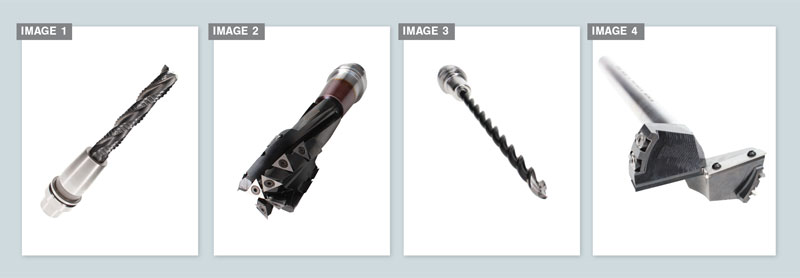
Image 2 shows a 61 mm diameter carbide insert router with indexable carbide inserts used in a wide variety of Mass Timber cutting tool designs. This geometry performs very well for larger diameter deep hole penetrations or slotting applications where a 40 mm solid carbide tool cannot be used. Carbide Inserts do provide a cost-effective solution, particularly in large diameter tool designs where extended cutting-edge lengths are required. Convenient replaceability features are beneficial for remote facilities, which do not have access to local sharpening services. However, carbide insert geometry is very limited compared to solid carbide helical router tools and will not perform at equivalent machine parameters. It is particularly difficult to manufacture carbide insert tooling at small diameters under 40 mm, due to design constraints limiting flute depth and shear angles. Therefore, careful consideration must be made when programming tools to limit depth of cut and feed rate.
Polycrystalline diamond
Machining abrasive CLT and GLT material in higher volume will lead to premature carbide cutting edge failure, regardless of machine parameters or application. Polycrystalline Diamond (PCD) tools provide a valuable alternative to carbide cutting edges. PCD will dramatically increase tool longevity, improve cut quality and avoid costly machine downtime. PCD cutting edges have proven to outlast carbide by 200 to 300 times in most applications, which is extremely beneficial in deep pocketing operations which generate excessive heat and stress on cutting tools.
Drilling applications
Effective and efficient hole drilling is critical to optimize workflow in mass timber machining operations. Drilling applications present interesting challenges for tool manufactures given the extreme size and depth variation of holes. Hole diameter sizes vary drastically as they are required for fastening systems, pass holes for mechanical and many other reasons. Most hole diameters 1.5 inch and under are machined with a drill bit and holes over 1.5 inch can often be machined with a router bit. However, maximum router tool projection is generally limited to 10 to 14 inches depending on diameter, which makes it impossible to use a router tool for holes over 14-inch depth.
In this case, a larger diameter carbide insert drill bit can be manufactured.
Image 3 shows a carbide tipped auger still drill bit for holes 1.25 inch and under.
Image 4 shows a large format carbide insert drill with shank extension to reach 16-inch depth of cut. This design is particularly useful for hole sizes 1.5-to-3.5-inch diameter.
Advanced tool holding systems
Although many tool designs can be manufactured on integrated HSK holders, there are some scenarios where tools need to be made separate from the tool holder.
Mechanical collets are the most common clamping system, but unfortunately, collets do have limited clamping force and accuracy ratings relative to other alternatives.
Due to excessive length and diameter requirements for mass timber tools, mechanical collets are not a viable option in most cases and should only be used for smaller diameter tools under 20 mm.
Image 1 and 2 shows a custom extended length shrink fit clamping system for advanced machining applications. Shrink fit clamping technology has been used for decades in metalworking and readily available in standard sizes. The extension provides optimal clamping performance and ability to reach difficult areas of complex mass timber components with router tools or drills.
Large diameter saw blades
One of the unique challenges of mass timber machining is the requirement for large diameter saw blades, which must be mounted on HSK holders to run on CNC routers.
Mounting saw blades on HSK connections is not a new concept; however, mass timber applications dramatically increase diameter requirement for saw blades, which pushes the design limits for machine and cutting tools. Saw blades are required to cut up to 12- to 16-inch-thick material in some scenarios, so the saw flanges and HSK connections must be designed to accommodate extremely deep cuts, without sacrificing safety. Many mass timber machines are equipped with chainsaw aggregate technology, which allows machines to cut thicker material; however, the chainsaw systems do not provide acceptable cut quality in many cases, therefore, saw blades are the preferred method for machining.
Some newer machinery models utilize a large 1,200 mm diameter saw blade to increase ability to cut through thick panels. Accurate balance in the manufacturing phase and careful attention to detail when assembling saw blades with HSK holders is critical to ensure safe operation of machinery.
Machine parameters
Given the wide variety of tool sizes and designs, machine parameters are difficult to generalize, but there are some basic principles, which can be beneficial when programming mass timber machinery. It is critical to optimize feed rate, to prevent heat generation and premature cutting-edge failure. Higher feed rates are always preferred to optimize tool life and minimize cycle times. Mass timber machinery is extremely robust and designed with maximum part clamping features to reduce vibration when cutting at high feed rates. Large mass timber components are generally heavy and easy to hold compared to smaller components in other industries, so hold down pressure is rarely a concern. Cutting tools and holders are often the limiting factor for feed rate optimization. Rigid holding systems combined with proper tool selection will allow feed rates to be maximized, but depth of cut must also be considered carefully. It can be dangerous to run high feed rates at deep depths as excessive forces are applied to machine spindles and cutting tools, which will cause premature tool failure and spindle wear. Machine programmers may be under pressure to reduce cycle time by increasing depth of cut, but in most cases, it is more practical to reduce depth of cut and increase feed rates to compensate for multiple passes. This programming strategy will generate less heat on the cutting tool and protect machinery from excessive spindle wear.
Conclusion
As mass manufacturing facilities continue to expand throughout North America, new production challenges will arise. New component designs and production efficiency requirements will change machinery designs and push the limits of tooling innovation. Mass timber equipment does require a higher-level tooling rigidity, balance and precision to perform during challenging machining operations. Proper tool selection and holding systems are critical to achieving optimal machine performance and cycle time reduction, while ensuring safe operation of all equipment. As mass timber components increase in size, machine and tool manufacturers must collaborate with mass timber partners to find better methods to manufacture components safely and efficiently to meet North American market demands.