Cross Laminated Timber (CLT) production continues to expand into North American markets as demand for alternative building materials and methods increases. Covid restrictions have had a negative impact on productivity and caused many project delays in the CLT industry, but as projects continue to come back on online, production demands will increase.
Volatility in softwood lumber markets has created pricing and production challenges in the short term; however, long-term demand projections are making CLT a viable building solution for the future.
Advanced machinery designs traditionally built for European markets, are being integrated into North American production facilities to machine CLT components in mass quantity.
Due to the large size of components, specialized equipment must be designed with extremely large footprints and production capacity. Cutting tools are also very specialized and must be designed with maximum rigidity and balance to ensure safe operation in demanding CLT applications. Cutting CLT components does involve a high rate of material removal at extreme depths of cut.
Therefore, saw blade and router tool formats must be extremely large to reach into deep cavities in the CLT parts.
 CLT material composition
Although most CLT materials are generally composed of softer wood species, the final product after glue lamination can be extremely abrasive to cut. Softwoods such as pine and Douglas fir, are relatively low density and easy to machine with all types of tools. However, many adhesive products now have high resin content, which generates heat during the machining process. This problem is exaggerated at deeper depths of cut with less efficient material removal rates. Heat generation causes premature cutting-edge failure, resulting in poor quality and added cutting pressures on the machine spindle and holding systems. Therefore, it is critical to design cutting tools and holding systems with added features to increase rigidity and balance.
Large diameter
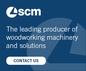
saw bladesOne of the unique challenges of CLT machining is the requirement for large diameter saw blades, which must be mounted on HSK holders.
Image 1 shows a 34-inch diameter saw blade mounted on HSK tool holder. Mounting saw blades on HSK connections is not a new concept, however, CLT applications dramatically increase diameter requirement for saw blades, which pushes the design limits for machine and cutting tools. Saw blades are required to cut up to 12 to 16-inch thick material in some scenarios, so the saw flanges and HSK connections must be designed to accommodate extremely deep cuts, without sacrificing safety. Many
CLT machines are equipped
with chainsaw aggregate technology, which allows machines to cut thicker material; however, the chainsaw systems do not provide acceptable cut quality in many cases, therefore, saw blades are the preferred method for machining.
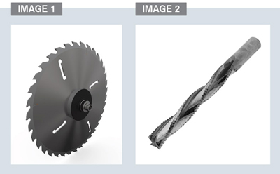
Extended Length Router ToolingSolid carbideImage 2 shows a 1-inch diameter by 12-inch long solid carbide router tool designed for deep machining in CLT components. Solid carbide geometry provides the absolute best cut quality and chip extraction when machining at high feed rates. Spiral flute geometry and serrated cutting edges reduces cutting pressures, improve cut quality and allow CLT machines to cut at an optimal feed rates to reduce cycle time.
However, they do have limitations with regards to diameter and length. Carbide raw material is expensive and difficult to produce at diameters over 1.5 inches and the cutting edge lengths are generally maximized at 10-inch length. Tools can be designed to cut 10-inch depth of cut, but the tools are susceptible to breakage depending on material density and quality.
Solid carbide spiral tools are also very complex to sharpen and repair, it can be challenging for facilities located in remote areas. It is imperative tools are sharpened on 5-axis CNC grinding machines, and verified for accuracy before use. If solid carbide tools are serviced properly, installed in rigid holding systems and used at proper machine parameters, they can provide optimal performance when machining narrow grooves or hole sizes.
Carbide insertAs tool diameter requirements increase over 1.5 inches, solid carbide is no longer a viable option. Carbide insert designs are a suitable alternative in some cases, but will perform very differently from solid carbide.
Image 3 shows a 4-inch diameter tool designed with replaceable carbide inserts fixed to an aluminum or steel body. Indexable carbide inserts are used in a wide variety of CLT cutting tool designs and perform very well in surfacing and hogging applications. Carbide inserts do provide a cost effective solution, particularly in large diameter tool designs where extended cutting edge lengths are required. Convenient replaceability features are beneficial for remote facilities, which do not have access to local sharpening service. However, carbide insert geometry is very limited compared to solid carbide helical router tools and will not perform at equivalent machine parameters. It is particularly difficult to manufacture carbide insert tooling at small diameters under 1.5 inches, due to design constraints limiting flute depth and shear angles. Therefore, careful consideration must be made when programming tools to limit depth of cut and feed rate.
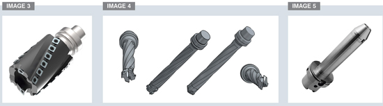
Polycrystalline diamondMachining abrasive CLT material in higher volume will lead to carbide cutting edge failure, regardless of machine parameters or application. Polycrystalline diamond (PCD) tools provide a valuable alternative to carbide cutting edges. PCD will dramatically increase tool longevity, improve cut quality and avoid costly machine downtime.
Image 4 shows a creative PCD solution, which includes a router and drilling option on one tool body. The tool is building on an integrated HSK holder for maximum rigidity and allows for replaceability cutting portion of the tool. PCD cutting edges have proven to outlast carbide by 200 to 300 times in most CLT applications.
Advanced tool
holding systemsAlthough many tool designs can be manufactured on integrated HSK holders, there are some scenarios where tools need to be made separated from the tool holder.
Mechanical collets are the most common clamping system, but unfortunately collets do have limited clamping force and accuracy ratings relative to other alternatives.
Due to excessive length and diameter requirements of CLT tools, mechanical collets are not a viable option in most cases and should only be used for smaller diameter tools under 3/4 inches.
Image 5 shows a custom, extended-length hydraulic clamping system for advanced CLT machining applications. Hydraulic clamping technology has been used for decades in metalworking and is readily available in standard sizes; however, this format includes a 10-inch long extension with precision hydro clamping interface at the end of the holder. Hydro clamping technology provides maximum clamping force and rigidity, which is required for larger tooling, especially when machining at higher feed rates. This custom extension system provides optimal clamping performance and ability to reach difficult areas of complex CLT parts.
Machine parametersGiven the wide variety of tool sizes and designs, machine parameters are difficult to generalize, but there are some basic principles, which can be beneficial when programming CLT machinery.
It is critical to optimize feed rate, in order to prevent heat generation and premature cutting edge failure. Higher feed rates are always preferred to optimize tool life and minimize cycle times.
CLT machinery is extremely robust and designed with maximum part clamping features to reduce vibration when cutting at high feed rates. Large CLT components are generally heavy and easy to hold compared to smaller components in other industries, so hold down pressure is rarely a concern. Cutting tools and holders are often the limiting factor for feed rate increases, but rigid holding systems combined with proper tool selection will allow feed rates to be maximized, but depth of cut (DOC) must also be considered carefully. It can be dangerous to run high feed rates at high DOC as excessive forces are applied to machine spindle and cutting tool, which will cause premature tool failure and spindle wear. Machine programmers may be under pressure to reduce cycle time by increasing depth of cut, but in most cases it is more practical to reduce depth of cut and increase feed rates to compensate for multiples passes. This programming strategy will generate less heat on the cutting tool and project machinery from excessive spindle wear.
ConclusionAs CLT manufacturing facilities continue to expand throughout North America, new production challenges will arise. New component designs and production efficiency requirements will change machinery designs and push the limits of tooling innovation. CLT equipment does require a higher level tooling rigidity, balance and precision to perform during challenging CLT applications. Proper tool selection and holding systems are critical to achieving optimal machine performance and cycle time reduction, while ensuring safe operation of all equipment.