As raw material price volatility continues and labour challenges persist, all companies are seeking ways to increase material yield and optimize production efficiency.
Much has been done in recent years to improve CNC router efficiency, but there are also opportunities on moulder machinery to improve cycle times and material savings. The images attached demonstrate different variations of moulder splitting applications. This process relies heavily on creative cutting tool design and proper machine configurations, to produce multiple components at the same time.
Splitting operations have been prominent in the softwood lumber industry for many years, but have recently gained more popularity in wood composites due to material price fluctuations and labour challenges.
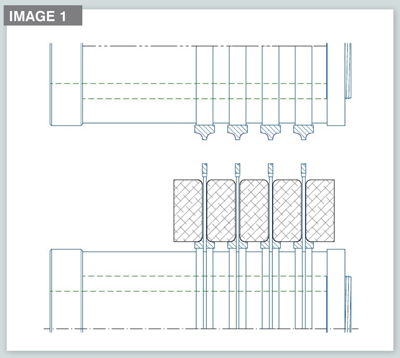
Image 1 shows a splitting application utilizing cutter heads, saw blades and hydro sleeves mounted on the last bottom spindle of moulder.
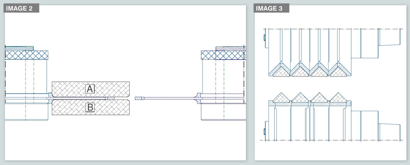
Image 2 shows a side-splitting application using the left and right spindles to split components A & B.
Image 3 shows multiple MDF components being machined from top and bottom spindles
Production efficiency Benefits are realized by running multiple parts through the moulder in one pass to reduce cycle time and dramatically increase moulder efficiency. Smaller parts are generally lower margin components, so production efficiency is critical to limit input costs. Effective splitting operations on moulders will also optimize other finishing and packaging processes down the line, as more parts can be produced with the same machine. Although machine and cutting tool set up can be complex and more time consuming, the initial labour investment will dramatically increase machine efficiency in the long term. As material and labour costs increase, it is imperative machining processes optimize material yield and machine performance.
CRITICAL CONSIDERATIONS Tool orientation The first decision in any splitting operation is the orientation of parts and associated tool design. There are two primary options, which affect tooling and machine design in different ways. Image 1 to 3 shows cutting tools performing final part splitting from the last bottom spindle, which means the parts travel through the entire machine in one piece until they reach the last bottom spindle. This strategy ensures the parts cannot move before the last spindle resulting in optimal cut quality. This method does require accurate set up to ensure multiple tools are aligned properly to avoid lines in the profile or other quality issues. Alternatively, the moulder can be designed to allow the cutting tools to project through the bottom of the material into the bed plate of the moulder. This requires special bed plates manufactured with abrasion resistant phenolic material for durability, and allows the tools to cut below the bed of the machine.
Tool holdingCutting tool assemblies for splitting applications generally involve multiple cutters and blades stacked up in a linear fashion to achieve multiple cuts in a single pass. It is imperative all the parts are held securely to avoid spinning on the machine spindle, causing tool or machine damage. Rather than stacking components individually on the machine spindle, parts should be mounted as an assembly on a sleeve to ensure effective operation and employee safety. Mechanical sleeves can be manufactured to hold all the cutting components using keyways or bolts as a safeguard. However, the best holding method is designed using a hydraulic clamping sleeve. The tools are mounted in the same manner as a mechanical sleeve, but hydraulic clamping pressure is utilized to secure the cutting tools to the sleeve and the sleeve to the machine spindle. This provides the absolute best machining scenario to ensure optimal machine performance and safety.
Material holding Securing components through the moulder is the most important machine consideration when setting up for splitting applications. It is impossible to achieve premium cut quality and machine efficiency without adequate hold down pressure on the components. As moulder feedrates are raised, it becomes increasingly difficult to hold the parts securely as material travels through the machine. Therefore, additional profiled pressure shoes and outfeed guides are needed to match the wood components and guide them accurately. Depending on profile design, the pressure shoes and guides will change. But holding pressure and outfeed guides must be designed and maintained properly to ensure parts move accurately and safely through the moulder.
Depth of cut Depth of cut will vary depending on profile specifications, but splitting applications generally involve deeper machining. Image 2 shows an extreme example of a side-splitting application using a saw blade with two-inch projection into the part. Components A & B will be separated by a custom moulder fence designed to maintain separation as the parts travel past the saw blades. Regardless of machine design, this operation will apply excessive force on
the cutting tools resulting
in heat generation and
added stresses on all components of the machine. Side-splitting operations
do require careful consideration and accurate machine set up to achieve acceptable results.
Feedrate Moulder splitting applications are generally performed at feedrates ranging from 60 to 300 feet per minute but can be done at higher feedrates in specific situations.
Once adequate hold down pressure is achieved and decisions about depth of cut are made, a final determination on feedrate can be decided.
Depth of cut and level of hold-down pressure are critical factors as they both have a direct impact on the ability to increase feedrates. Higher tool projection and depth of cut will necessitate lower feedrates depending on the spindle horsepower and cutting tool limitations.
Some machinery is equipped with dedicated split-saw spindles, which have higher horsepower and do allow for larger diameter tooling in specific situations. Machine configurations with two vertical spindles on both sides of the moulder are also available which allows for greater machining flexibility from the side of parts. This can be a great advantage when trying to machine at higher depths of cut and feedrates. Double side spindles designs are particularity useful in situations illustrated in Image 2, where extremely high depth of cut is required to project into wider parts. In this situation, the first vertical spindle can take half of the total depth of cut and then finish the complete cut on the second vertical spindle. Double spindle approach effectively reduces problems associated with extreme cutting depths and allows the moulder to operate at higher feedrates.
CONCLUSION Splitting applications do require substantial investment in proper machinery and tooling solutions to ensure success. Machinery and tooling integrations can be complex and will require substantial labour to set up and maintain operational efficiency. However, splitting operations have proven to increase machine and labour efficiency while optimizing material yield. As manufacturing markets continue to evolve, consider splitting applications for your moulder operations.